
Figure 7.1: 3D volume data and grid partitioning
The Marching Cubes method is one of the volume rendering methods, and is an algorithm that converts 3D voxel data filled with scalar data into polygon data. The first paper was published in 1987 by William E. Lorensen and Harvey E. Cline.
The Marching Cubes method was patented, but since it expired in 2005, it is now free to use.
First, divide the volume data space with a 3D grid.
Figure 7.1: 3D volume data and grid partitioning
Next, let's take out one of the divided grids. The boundaries of the eight vertices are calculated as 1 if the values of the eight corners of the grid are above the threshold and 0 if they are below the threshold.
The figure below shows the flow when the threshold is set to 0.5.

Figure 7.2: Determining the boundary according to the value of the angle
There are 256 types of combinations of the eight corners, but if you make full use of rotation and inversion, it will fit in 15 types. Assign triangular polygon patterns corresponding to the 15 types of combinations.

Figure 7.3: Combination of corners
The sample projects described in this chapter can be found in Assets / GPU ArchingCubes under Unity Graphics Programming's Unity Project https://github.com/IndieVisualLab/UnityGraphicsProgramming.
For implementation, I ported it to Unity by referring to Paul Bourke's Polygonising a scalar field site * 1 .
[*1] Polygonising a scalar field http://paulbourke.net/geometry/polygonise/
This time, I will explain along with this sample project.
There are three main implementations.
First, create from the GPU ArchingCubesDrawMesh class that initializes the mesh and registers the drawing .
As explained in the previous section, the Marching cubes method is an algorithm that generates polygons by combining the eight corners of the grid. To do that in real time, you need to dynamically create polygons.
However, it is inefficient to generate a mesh vertex array on the CPU side (C # side) every frame.
So we use Geometry Shader. GeometryShader is a Shader located between VertexShader and FragmentShader, which can increase or decrease the number of vertices processed by VertexShader.
For example, you can add 6 vertices around one vertex to generate a plate polygon.
Furthermore, it is very fast because it is processed on the Shader side (GPU side).
This time, I will use Geometry Shader to generate and display Marching Cubes polygons.
First, define the variables used in the GPUMarchingCubesDrawMesh class.
Listing 7.1: Definition of variables
using UnityEngine;

public class GPUMarchingCubesDrawMesh : MonoBehaviour {

    #region public
    public int segmentNum = 32; // Number of divisions on one side of the grid

    [Range(0,1)]
    public float threashold = 0.5f; // Threshold for the scalar value to mesh
    public Material mat; // Material for rendering

    public Color DiffuseColor = Color.green; // Diffuse color
    public Color EmissionColor = Color.black; // Emission color
    public float EmissionIntensity = 0; // Emission intensity

    [Range(0,1)]
    public float metallic = 0; // metallic feeling
    [Range(0, 1)]
    public float glossiness = 0.5f; // Glossiness
    #endregion

     #region private
    int vertexMax = 0; // number of vertices
    Mesh[] meshs = null;                        // Mesh配列
    Material [] materials = null; // Material array for each mesh
    float renderScale = 1f / 32f; // Display scale
    MarchingCubesDefines mcDefines = null; // Constant array group for MarchingCubes
    #endregion

}
Next, create a mesh to pass to the Geometry Shader. The vertices of the mesh should be placed one by one in the divided 3D grid. For example, if the number of divisions on one side is 64, 64 * 64 * 64 = 262,144 vertices are required.
However, in Unity2017.1.1f1, the maximum number of vertices in one mesh is 65,535. Therefore, each mesh is divided so that the number of vertices is within 65,535.
Listing 7.2: Meshing part
void Initialize()
{
  vertexMax = segmentNum * segmentNum * segmentNum;

  Debug.Log("VertexMax " + vertexMax);

  // Divide the size of 1Cube by segmentNum to determine the size at the time of rendering
  renderScale = 1f / segmentNum;

  CreateMesh();

  // Initialize constant array for Marching Cubes used in shader
  mcDefines = new MarchingCubesDefines();
}

void CreateMesh()
{
  // Since the maximum number of vertices of Mesh is 65535, divide Mesh
  int vertNum = 65535;
  int meshNum = Mathf.CeilToInt ((float) vertexMax / vertNum); // Number of meshes to split
  Debug.Log("meshNum " + meshNum );

  meshs = new Mesh[meshNum];
  materials = new Material[meshNum];

  // Mesh bounce calculation
  Bounds bounds = new Bounds(
    transform.position,
    new Vector3(segmentNum, segmentNum, segmentNum) * renderScale
  );

  int id = 0;
  for (int i = 0; i < meshNum; i++)
  {
    // Vertex creation
    Vector3[] vertices = new Vector3[vertNum];
    int[] indices = new int[vertNum];
    for(int j = 0; j < vertNum; j++)
    {
      vertices[j].x = id % segmentNum;
      vertices[j].y = (id / segmentNum) % segmentNum;
      vertices [j] .z = (id / (segmentNum * segmentNum))% segmentNum;

      indices[j] = j;
      id++;
    }

    // Mesh creation
    meshs[i] = new Mesh();
    meshs[i].vertices = vertices;
    // Mesh Topology can be Points because polygons are created with Geometry Shader
    meshs[i].SetIndices(indices, MeshTopology.Points, 0);
    meshs[i].bounds = bounds;

    materials[i] = new Material(mat);
  }
}
The source MarchingCubesDefinces.cs defines a constant array used for rendering the Marching Cubes method and a ComputeBuffer for passing the constant array to the shader. ComputeBuffer is a buffer that stores data used by shaders. Since the data is stored in the memory on the GPU side, it is quickly accessible from the shader.
In fact, the constant array used in the rendering of the Marching Cubes method can be defined on the shader side. However, the reason why the constant array used in the shader is initialized on the C # side is that the shader has a limitation that the number of literal values (directly written values) can only be registered up to 4096. If you define a huge array of constants in your shader, you will quickly reach the upper limit of the number of literal values.
Therefore, by storing it in ComputeShader and passing it, it will not be a literal value, so it will not hit the upper limit. Therefore, the number of processes increases a little, but on the C # side, the constant array is stored in ComputeBuffer and passed to the shader.
Listing 7.3: ComputeBuffer initialization part
void Initialize()
{
  vertexMax = segmentNum * segmentNum * segmentNum;

  Debug.Log("VertexMax " + vertexMax);

  // Divide the size of 1Cube by segmentNum to determine the size at the time of rendering
  renderScale = 1f / segmentNum;

  CreateMesh();

  // Initialize constant array for Marching Cubes used in shader
  mcDefines = new MarchingCubesDefines();
}
In the Initialize () function mentioned earlier, MarchingCubesDefines is initialized.
Next is the function that calls the rendering process.
This time, I'll use Graphics.DrawMesh () to render multiple meshes at once and to be affected by Unity's lighting. The meaning of DiffuseColor etc. defined in the public variable will be explained in the explanation on the shader side.
The ComputeBuffers of the MarchingCubesDefines class in the previous section are passed to the shader with material.setBuffer.
Listing 7.4: Rendered part
void RenderMesh()
{
  Vector3 halfSize = new Vector3(segmentNum, segmentNum, segmentNum)
                     * renderScale * 0.5f;
  Matrix4x4 trs = Matrix4x4.TRS(
                     transform.position,
                     transform.rotation,
                     transform.localScale
                  );

  for (int i = 0; i < meshs.Length; i++)
  {
    materials[i].SetPass(0);
    materials[i].SetInt("_SegmentNum", segmentNum);
    materials[i].SetFloat("_Scale", renderScale);
    materials[i].SetFloat("_Threashold", threashold);
    materials[i].SetFloat("_Metallic", metallic);
    materials[i].SetFloat("_Glossiness", glossiness);
    materials[i].SetFloat("_EmissionIntensity", EmissionIntensity);

    materials[i].SetVector("_HalfSize", halfSize);
    materials[i].SetColor("_DiffuseColor", DiffuseColor);
    materials[i].SetColor("_EmissionColor", EmissionColor);
    materials[i].SetMatrix("_Matrix", trs);

    Graphics.DrawMesh(meshs[i], Matrix4x4.identity, materials[i], 0);
  }
}
Listing 7.5: Calling Part
// Use this for initialization
void Start ()
{
  Initialize();
}

void Update()
{
  RenderMesh ();
}
Start () calls Initialize () to generate a mesh, and the Update () function calls RenderMesh () to render.
The reason for calling RenderMesh () with Update () is that Graphics.DrawMesh () does not draw immediately, but it feels like "registering for rendering process once".
By registering, Unity will adapt the lights and shadows. A similar function is Graphics.DrawMeshNow (), but it draws instantly, so Unity lights and shadows are not applied. Also, you need to call it with OnRenderObject () or OnPostRender () instead of Update ().
The shader this time is roughly divided into two parts, the " rendering part of the entity" and the "rendering part of the shadow" . In addition, three shader functions are executed within each, the vertex shader, the geometry shader, and the fragment shader.
Since the shader source is long, I will have the sample project look at the entire implementation, and I will explain only the important points. The shader file described is GPU ArchingCubesRenderMesh.shader.
At the top of the shader, we define the structure used for rendering.
Listing 7.6: Structure Definition Part
// Vertex data coming from the mesh
struct appdata
{
  float4 vertex: POSITION; // vertex coordinates
};

// Data passed from the vertex shader to the geometry shader
struct v2g
{
  float4 pos: SV_POSITION; // Vertex coordinates
};

// Data passed from the geometry shader to the fragment shader when rendering the entity
struct g2f_light
{
  float4 pos: SV_POSITION; // Local coordinates
  float3 normal: NORMAL; // normal
  float4 worldPos: TEXCOORD0; // World coordinates
  half3 sh        : TEXCOORD3;    // SH
};

// Data passed from the geometry shader to the fragment shader when rendering shadows
struct g2f_shadow
{
  float4 pos: SV_POSITION; // coordinate
  float4 hpos     : TEXCOORD1;
};
Next, we are defining variables.
Listing 7.7: Variable definition part
int _SegmentNum;

float _Scale;
float _Threashold;

float4 _DiffuseColor;
float3 _HalfSize;
float4x4 _Matrix;

float _EmissionIntensity;
half3 _EmissionColor;

half _Glossiness;
half _Metallic;

StructuredBuffer<float3> vertexOffset;
StructuredBuffer<int> cubeEdgeFlags;
StructuredBuffer<int2> edgeConnection;
StructuredBuffer<float3> edgeDirection;
StructuredBuffer<int> triangleConnectionTable;
The contents of various variables defined here are passed by the material.Set ○○ function in the RenderMesh () function on the C # side. ComputeBuffers in the MarchingCubesDefines class have changed their type names to StructuredBuffer <○○>.
The vertex shader is very simple, as most of the work is done by the geometry shader. It simply passes the vertex data passed from the mesh to the geometry shader as is.
Listing 7.8: Vertex shader implementation
// Vertex data coming from the mesh
struct appdata
{
  float4 vertex: POSITION; // vertex coordinates
};

// Data passed from the vertex shader to the geometry shader
struct v2g
{
  float4 pos: SV_POSITION; // coordinate
};

// Vertex shader
v2g vert(appdata v)
{
  v2g or = (v2g) 0;
  o.pos = v.vertex;
  return o;
}
By the way, the vertex shader is common to the entity and the shadow.
Since it is long, I will explain it while dividing it.
Listing 7.9: Function declaration part of the geometry shader
// Entity geometry shader
[maxvertexcount (15)] // Definition of the maximum number of vertices output from the shader
void geom_light(point v2g input[1],
                inout TriangleStream<g2f_light> outStream)
First is the declaration part of the geometry shader.
[maxvertexcount(15)]Is the definition of the maximum number of vertices output from the shader. With the algorithm of the Marching Cubes method this time, a maximum of 5 triangular polygons can be created per grid, so a total of 15 vertices are output in 3 * 5.
Therefore, write 15 in () of maxvertexcount.
Listing 7.10: Scalar value acquisition part of the eight corners of the grid
float cubeValue [8]; // Array for getting scalar values at the eight corners of the grid
// Get the scalar values for the eight corners of the grid
for (i = 0; i < 8; i++) {
cubeValue[i] = Sample(
pos.x + vertexOffset[i].x,
pos.y + vertexOffset [i] .y,
pos.z + vertexOffset [i] .z
);
}
pos contains the coordinates of the vertices placed in the grid space when creating the mesh. As the name implies, vertexOffset is an array of offset coordinates added to pos.
This loop gets the scalar values in the volume data of the coordinates of the eight corners of one vertex = one grid. vertexOffset points to the order of the corners of the grid.

Figure 7.4: Order of grid corner coordinates
Listing 7.11: Sampling function part
// sampling function
float Sample(float x, float y, float z) {

  // Are the coordinates out of the grid space?
  if ((x <= 1) ||
      (y <= 1) ||
      (z <= 1) ||
      (x >= (_SegmentNum - 1)) ||
      (y >= (_SegmentNum - 1)) ||
      (z> = (_SegmentNum - 1))
     )
    return 0;

  float3 size = float3(_SegmentNum, _SegmentNum, _SegmentNum);

  float3 pos = float3(x, y, z) / size;

  float3 spPos;
  float result = 0;

  // Distance function of 3 spheres
  for (int i = 0; i < 3; i++) {
    float sp = -sphere(
      pos - float3(0.5, 0.25 + 0.25 * i, 0.5),
      0.1 + (sin (_Time.y * 8.0 + i * 23.365) * 0.5 + 0.5) * 0.025) + 0.5;
    result = smoothMax(result, sp, 14);
  }

  return result;
}
This function fetches the scalar value of the specified coordinates from the volume data. This time, instead of using a huge amount of 3D volume data, we will calculate the scalar value using a simple algorithm that uses a distance function.
The 3D shape drawn by the Marching Cubes method this time is defined using what is called a "distance function" .
The distance function here is, roughly speaking, a "function that satisfies the distance condition".
For example, the distance function of a sphere is:
Listing 7.12: Sphere Distance Function
inline float sphere(float3 pos, float radius)
{
    return length(pos) - radius;
}
Coordinates are entered in pos, but consider the case where the center coordinates of the sphere are the origin (0,0,0). radius is the radius.
The length is calculated by length (pos), but this is the distance between the origin and pos, and it is subtracted by the radius radius, so if the length is less than the radius, it is a natural but negative value.
In other words, if you pass the coordinates pos and a negative value is returned, you can judge that the coordinates are inside the sphere.
The advantage of the distance function is that it is easy to make the program small because the figure can be expressed with a simple calculation formula of several lines. You can find a lot of information about other distance functions on Inigo Quilez's site.
http://iquilezles.org/www/articles/distfunctions/distfunctions.htm
Listing 7.13: A composite of the distance functions of three spheres
// Distance function of 3 spheres
for (int i = 0; i < 3; i++) {
  float sp = -sphere(
    pos - float3(0.5, 0.25 + 0.25 * i, 0.5),
    0.1 + (sin (_Time.y * 8.0 + i * 23.365) * 0.5 + 0.5) * 0.025) + 0.5;
  result = smoothMax(result, sp, 14);
}
This time, 8 corners (vertices) of 1 square of the grid are used as pos. The distance from the center of the sphere is treated as it is as the density of the volume data.
As will be described later, the sign is inverted because it is polygonized when the threshold value is 0.5 or more. In addition, the coordinates are slightly shifted to obtain the distances to the three spheres.
Listing 7.14: smoothMax function
float smoothMax(float d1, float d2, float k)
{
  float h = exp(k * d1) + exp(k * d2);
  return log(h) / k;
}
smoothMax is a function that blends the results of distance functions nicely. You can use this to fuse the three spheres like a metaball.
Listing 7.15: Threshold Check
// Check if the values at the eight corners of the grid exceed the threshold
for (i = 0; i < 8; i++) {
if (cubeValue[i] <= _Threashold) {
flagIndex |= (1 << i);
}
}
int edgeFlags = cubeEdgeFlags[flagIndex];
// Do not draw anything if empty or completely filled
if ((edgeFlags == 0) || (edgeFlags == 255)) {
return;
}
If the scalar value at the corner of the grid exceeds the threshold, set a bit in flagIndex. Using the flagIndex as an index, the information for generating polygons is extracted from the cubeEdgeFlags array and stored in edgeFlags. If all corners of the grid are below or above the threshold, it is completely inside or outside and no polygons are generated.
Listing 7.16: Polygon Vertex Coordinate Calculation
float offset = 0.5;
float3 vertex;
for (i = 0; i < 12; i++) {
  if ((edgeFlags & (1 << i)) != 0) {
    // Get the threshold offset between the corners
    offset = getOffset(
               cubeValue[edgeConnection[i].x],
               cubeValue[edgeConnection[i].y], _
               Threashold
             );

    // Complement the coordinates of the vertices based on the offset
    vertex = vertexOffset[edgeConnection[i].x]
             + offset * edgeDirection[i];

    edgeVertices[i].x = pos.x + vertex.x * _Scale;
    edgeVertices [i] .y = pos.y + vertex.y * _Scale;
    edgeVertices [i] .z = pos.z + vertex.z * _Scale;

    // Normal calculation (requires vertex coordinates before scaling to resample)
    edgeNormals [i] = getNormal (
                        defpos.x + vertex.x,
                        defpos.y + vertex.y,
                        defpos.z + vertex.z
                     );
  }
}
This is where the vertex coordinates of the polygon are calculated. Looking at the bit of edgeFlags earlier, we are calculating the vertex coordinates of the polygon to be placed on the edge of the grid.
getOffset gives the ratio (offset) from the current corner to the next corner from the scalar values and thresholds of the two corners of the grid. By offsetting the coordinates of the current corner toward the next corner by offset, the polygon will eventually become smooth.
In getNormal, the normal is calculated by re-sampling and calculating the gradient.
Listing 7.17: Concatenate vertices to make a polygon
// Concatenate vertices to create polygons
int vindex = 0;
int findex = 0;
// Create up to 5 triangles
for (i = 0; i < 5; i++) {
  findx = flagIndex * 16 + 3 * i;
  if (triangleConnectionTable[findex] < 0)
    break;

  // make a triangle
  for (j = 0; j < 3; j++) {
    vindex = triangleConnectionTable[findex + j];

    // Multiply the Transform matrix to convert to world coordinates
    float4 ppos = mul(_Matrix, float4(edgeVertices[vindex], 1));
    o.pos = UnityObjectToClipPos(ppos);

    float3 norm = UnityObjectToWorldNormal(
                    normalize(edgeNormals[vindex])
                  );
    o.normal = normalize(mul(_Matrix, float4(norm,0)));

    outStream.Append (o); // Append vertices to strip
  }
  outStream.RestartStrip (); // Break once and start the next primitive strip
}
This is the place where the polygon is made by connecting the vertex coordinate groups obtained earlier. triangleConnectionTable Contains the indexes of the vertices that connect to the array. Multiply the vertex coordinates by the Transform matrix to convert to world coordinates, and then use UnityObjectToClipPos () to convert to screen coordinates.
Also, UnityObjectToWorldNormal () converts the normals to the world coordinate system. These vertices and normals will be used for lighting in the next fragment shader.
TriangleStream.Append () and RestartStrip () are special functions for geometry shaders. Append () adds vertex data to the current strip. RestartStrip () creates a new strip. Since it is a Triangle Stream, it is an image to append up to 3 on one strip.
In order to reflect the lighting such as GI (Global Illumination) of Unity, the lighting processing part of Surface Shader after Generate code is ported.
Listing 7.18: Fragment Shader Definition
// Entity fragment shader
void frag_light(g2f_light IN,
  out half4 outDiffuse        : SV_Target0,
  out half4 outSpecSmoothness : SV_Target1,
  out half4 outNormal         : SV_Target2,
  out half4 outEmission       : SV_Target3)
There are 4 outputs (SV_Target) to output to G-Buffer.
Listing 7.19: Initializing the SurfaceOutputStandard structure
#ifdef UNITY_COMPILER_HLSL
  SurfaceOutputStandard o = (SurfaceOutputStandard)0;
#else
  SurfaceOutputStandard o;
#endif
  o.Albedo = _DiffuseColor.rgb;
  o.Emission = _EmissionColor * _EmissionIntensity;
  o.Metallic = _Metallic;
  o.Smoothness = _Glossiness;
  o.Alpha = 1.0;
  o.Occlusion = 1.0;
  o.Normal = normal;
Set parameters such as color and gloss to the SurfaceOutputStandard structure that will be used later.
Listing 7.20: GI-related processing
// Setup lighting environment
UnityGI gi;
UNITY_INITIALIZE_OUTPUT(UnityGI, gi);
gi.indirect.diffuse = 0;
gi.indirect.specular = 0;
gi.light.color = 0;
gi.light.dir = half3 (0, 1, 0);
gi.light.ndotl = LambertTerm(o.Normal, gi.light.dir);

// Call GI (lightmaps/SH/reflections) lighting function
UnityGIInput giInput;
UNITY_INITIALIZE_OUTPUT(UnityGIInput, giInput);
giInput.light = gi.light;
giInput.worldPos = worldPos;
giInput.worldViewDir = worldViewDir;
giInput.atten = 1.0;

giInput.ambient = IN.sh;

giInput.probeHDR[0] = unity_SpecCube0_HDR;
giInput.probeHDR[1] = unity_SpecCube1_HDR;

#if UNITY_SPECCUBE_BLENDING || UNITY_SPECCUBE_BOX_PROJECTION
// .w holds lerp value for blending
giInput.boxMin[0] = unity_SpecCube0_BoxMin;
#endif

#if UNITY_SPECCUBE_BOX_PROJECTION
giInput.boxMax[0] = unity_SpecCube0_BoxMax;
giInput.probePosition [0] = unity_SpecCube0_ProbePosition;
giInput.boxMax[1] = unity_SpecCube1_BoxMax;
giInput.boxMin[1] = unity_SpecCube1_BoxMin;
giInput.probePosition [1] = unity_SpecCube1_ProbePosition;
#endif

LightingStandard_GI (o, giInput, gi);
GI related processing. I put the initial value in UnityGIInput and write the result of GI calculated by LightnintStandard_GI () to UnityGI.
Listing 7.21: Calculation of light reflection
// call lighting function to output g-buffer
outEmission = LightingStandard_Deferred(o, worldViewDir, gi,
                                        outDiffuse,
                                        outSpecSmoothness,
                                        outNormal);
outDiffuse.a = 1.0;

#ifndef UNITY_HDR_ON
outEmission.rgb = exp2(-outEmission.rgb);
#endif
Pass the calculation results to LightingStandard_Deferred () to calculate the degree of light reflection and write it to the Emission buffer. In the case of HDR, write after sandwiching the part compressed by exp.
It's almost the same as the actual geometry shader. I will explain only where there are differences.
Listing 7.22: Shadow Geometry Shader
int vindex = 0;
int findex = 0;
for (i = 0; i < 5; i++) {
  findx = flagIndex * 16 + 3 * i;
  if (triangleConnectionTable[findex] < 0)
    break;

  for (j = 0; j < 3; j++) {
    vindex = triangleConnectionTable[findex + j];

    float4 ppos = mul(_Matrix, float4(edgeVertices[vindex], 1));

    float3 norm;
    norm = UnityObjectToWorldNormal(normalize(edgeNormals[vindex]));

    float4 lpos1 = mul(unity_WorldToObject, ppos);
    o.pos = UnityClipSpaceShadowCasterPos (lpos1,
                                            normalize(
                                              mul(_Matrix,
                                                float4(norm, 0)
                                              )
                                            )
                                          );
    o.pos = UnityApplyLinearShadowBias (o.pos);
    o.hpos = o.pos;

    outStream.Append(o);
  }
  outStream.RestartStrip();
}
Convert the vertex coordinates to the coordinates of the shadow projection destination with UnityClipSpaceShadowCasterPos () and UnityApplyLinearShadowBias ().
Listing 7.23: Shadow Fragment Shader
// Shadow Fragment Shader
fixed4 frag_shadow(g2f_shadow i) : SV_Target
{
  return i.hpos.z / i.hpos.w;
}
It's too short to explain. Actually, the shadow is drawn normally even with return 0 ;. Is Unity doing a good job inside?
When you run it, you should see a picture like this.
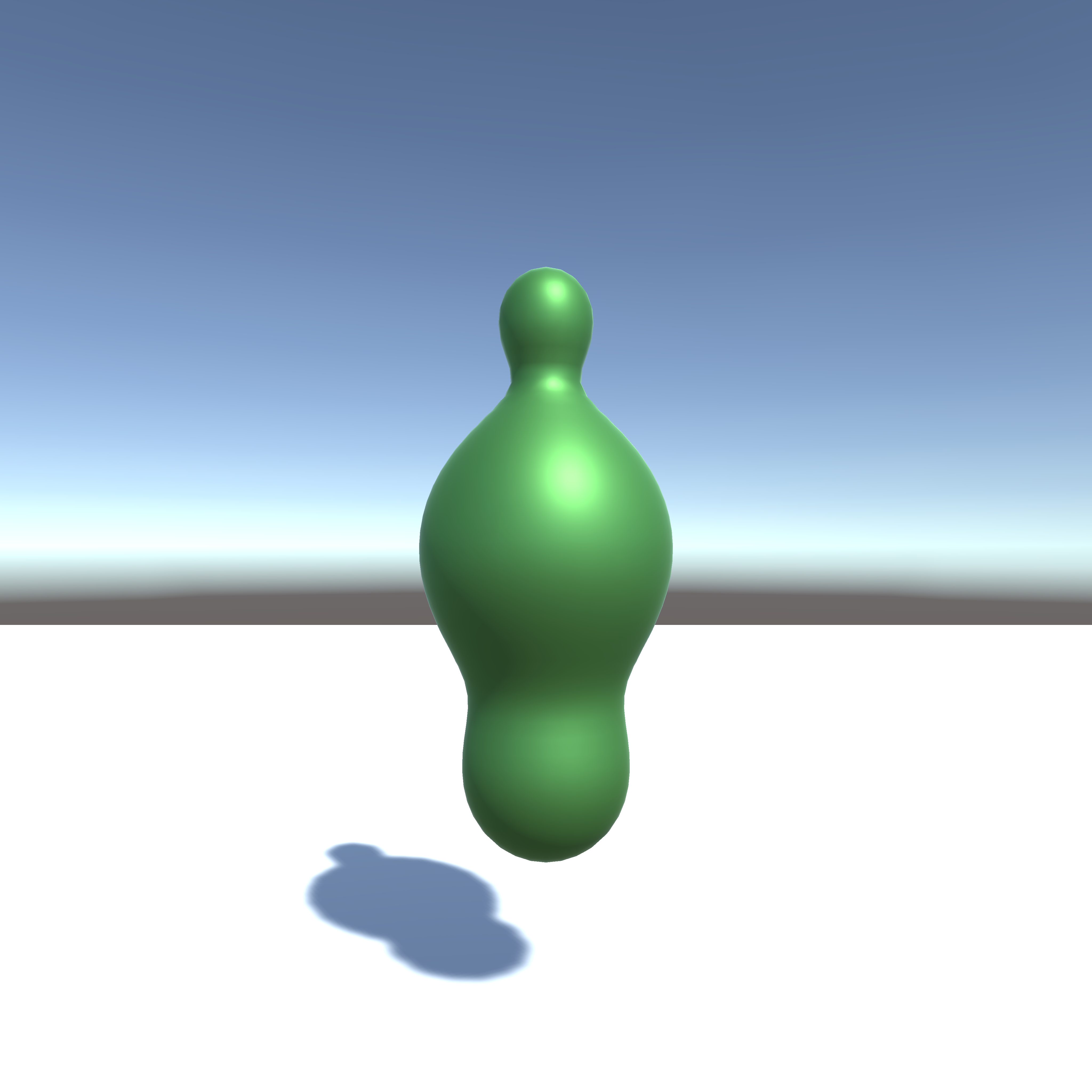
Figure 7.5: undulation
Also, various shapes can be created by combining distance functions.
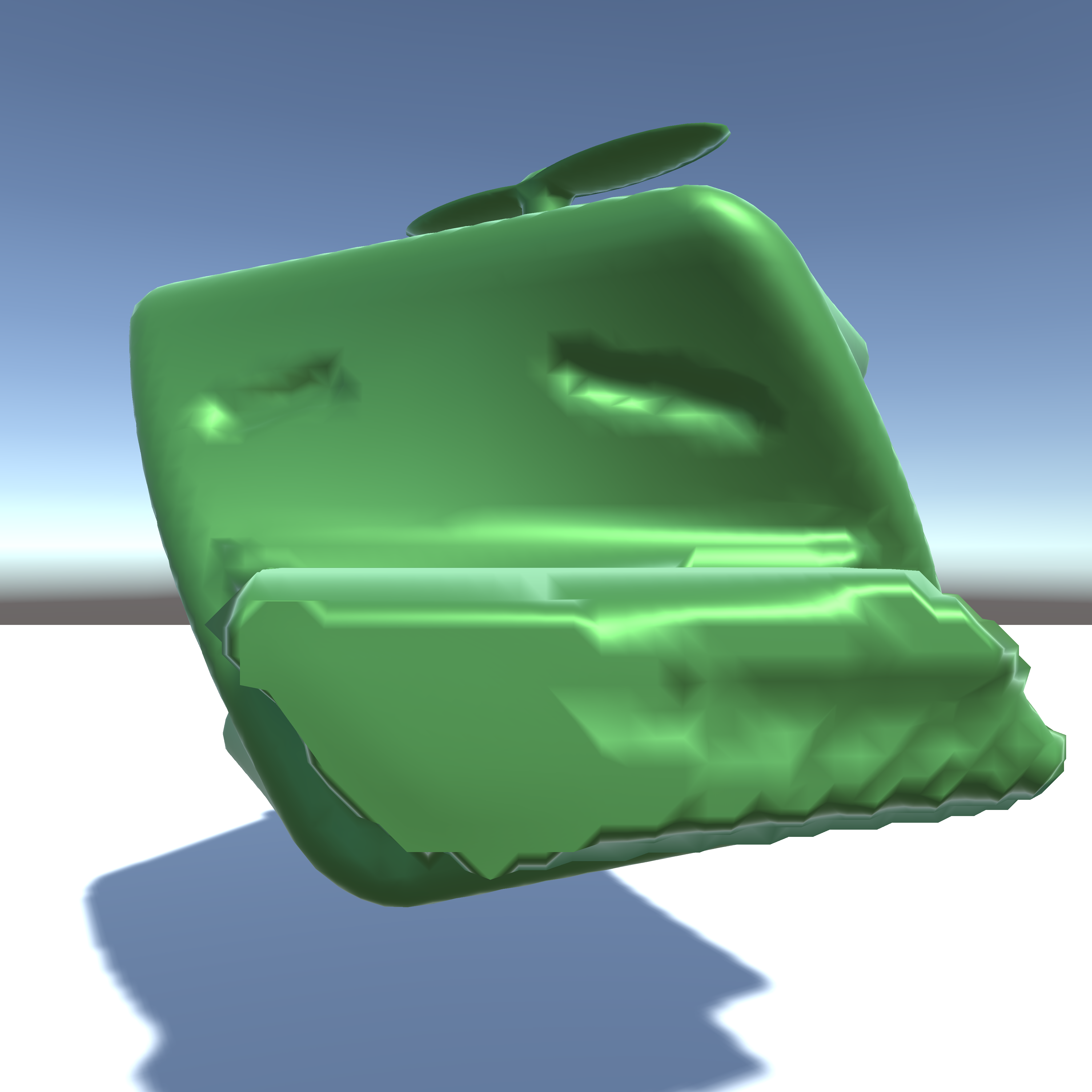
Figure 7.6: Kaiware daikon
This time I used the distance function for simplification, but I think that the Marching cubes method can also be used to use 3D textures with volume data written in them and to visualize various 3D data. ..
For game use, you may be able to create games like ASTORONEER * 2 , which allows you to dig and build terrain .
Everyone, please try to find various expressions with the Marching Cubes method!
http://iquilezles.org/www/articles/distfunctions/distfunctions.htm
[* 2] ASTRONEER http://store.steampowered.com/app/361420/ASTRONEER/?l=japanese